

Few Things Must to Know About Pressure Relief Valve

The Pressure Relief Valve is also known as a safety valve, safety relief valve, and PRV in short form. There are many advantages of PRV as we discussed in our previous article Importance of PRV in High Rise Buildings. Here we explore the history of Pressure Reducing Valve and its operation. The following topics will also increase your knowledge about the pressure relief valve.
Pressure Relief Valve History
The pressure relief valve opens when a preset pressure is reached, discharging fluid until the pressure drops to a safe level. How the safety relief valve came about is an interesting story.
The first pressure relief valve was invented by Denis Papin (circa 1679) for his steam-powered “digester” to prevent overpressure. An arm with a weight suspended from it served as a pressure relief device. To open the valve, the steam pressure acting on the valve had to be greater than the weight acting on the lever arm. The design of a relief pressure setting requiring a longer lever arm and/or heavier weight required a longer lever arm. Even though this simple system worked, there was a need for more space, and it was easy to tamper with, leading to a possible explosion. An additional disadvantage was a premature opening of the valve if the device was subjected to bouncing movements.
Direct-acting deadweight pressure relief valves:
On early steam locomotives, direct-acting deadweight pressure relief valves were installed to avoid the disadvantages of the lever arrangement. This design applied weights directly to the top of the valve mechanism. The valve size was often undersized to maintain a reasonable weight range, resulting in a smaller vent opening than was required. In many cases, an explosion occurred when the steam pressure rose faster than the vent was able to release. Additionally, bouncing movements prematurely released the pressure.
Direct acting spring valves
It is thought that Timothy Hackworth used direct acting spring valves on his locomotive engine, called the Royal George (circa 1828). To apply force to the valve, Timothy used leaf springs arranged in accordion fashion. Leaf springs would later be replaced with coil springs. It is possible to adjust the spring force by adjusting the nuts holding the leaf springs in place.
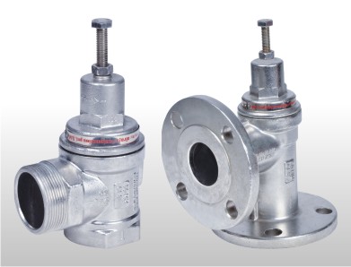
Pressure Relief Valve
In response to the widespread use of steam boilers for powering locomotives, riverboats, and pumps, the direct acting spring relief valve design continued to be refined in subsequent years. Despite steam boilers being less common today, the safety relief valve continues to be a crucial component for protection against catastrophic failure in systems with pressure vessels.
Let’s take a closer look at how a typical direct acting pressure relief valve works.
Working Pressure Relief Valves
Pressure relief valves consist of three functional elements:
- Valve element, normally a spring loaded poppet valve.
- Sensing element, normally a diaphragm or piston.
- Reference force element. generally a spring.
During operation, the pressure relief valve remains closed until the desired pressure is reached upstream. As the pressure reaches the set point, the valve will begin to crack open, allowing more flow to pass through as the overpressure increases. When the upstream pressure drops below the set pressure, the valve closes again.
Valve Element
As a valve element, pressure relief valves are commonly made with spring-loaded “poppet” valves. For high-pressure valve designs, the poppet has an elastomeric seal or a thermoplastic seal that seals the valve seat. The spring and the upstream pressure exert opposing forces on the valve when it is operating. Upstream pressure exerts a greater force than the spring power, which causes the poppet to move away from the valve seat, which allows fluid to pass through the outlet port. The valve closes when the upstream pressure falls below the set point.
Sensing element
In many cases, piston-style designs are chosen when higher relief pressures are needed, when ruggedness is an issue, or when tight tolerances are not required. Due to friction from the piston seal, piston designs tend to be slower than diaphragm designs. The diaphragm style is preferred for low pressure applications, or when high accuracy is necessary. Pressure changes are sensed by a thin disc shaped element in a diaphragm relief valve. For special applications, thin convoluted metal is used instead of an elastomer. With piston style designs, friction is effectively eliminated by diaphragms. Moreover, it is often possible to design a relief valve diaphragm that provides a greater sensing area than a piston style design for a particular relief valve size.
Reference Force Element
Mechanical springs are usually used as reference force elements. The spring pushes against the sensing element, closing the valve. It is common for pressure relief valves to be designed with an adjustment that allows the set-point for relief pressure to be adjusted by varying the force exerted by the reference spring.
Conclusion
Pressure relief valve working is a process of monitoring the pressure in the system, if the pressure goes beyond the set limits then the pressure is reduced to the safe range. The pressure relief valve is one of the most important parts of the process since it acts as a safety valve. Its operation is based on the principle of the diaphragm. If the pressure exceeds the set limits, the diaphragm moves and opens the valve. Pressure relief valve working is a simple process of monitoring the pressure in the system, if the pressure exceeds the set limits then the pressure is reduced to the safe range. Blog topic: How to prevent mosquito bites: A blog about how to prevent mosquito bites.