

Hello Everyone, yesterday aira’s head engineer Mr. Reddy organized a workshop about industrial valves for the Mechanical students. At that time, one of those students asked an interesting question to Mr. Reddy. The guy asked, “What is the basic mechanism of industrial valves? How are the valves developing to date?”
Mr. Reddy appreciated the guy for asking the question and replied there are major four types of the main valve mechanism. The first one is Parallel movement. In this type of mechanism, the inlet port is closed by a plug and the Globe Valve is its best example. The other one is the Sliding movement. You can easily spot it at Gate Valves. The third one is the Pinching movement which is used in the Diaphragm valve. Last but not least, is the Rotary movement mechanism. Ball Valve, Butterfly Valve, and Plug Valve are perfect examples of this. And he added that valves are being developed by engineers more and more as per the requirement.
After the workshop ended all went to their place, but the guy’s question put a spark in my mind. I realized that there are so many people who are not aware of industrial valves and their types. Maybe they want to know about it but I found there is not much data available on the internet as well. So I decided to write a full detailed article for the knowledge seekers. If you are interested in knowing all things about valves then this article is for you. So let’s start with the most common Ball Valves.
Ball Valve
Ball Valves are one of the quarter-turn family valves. They only require a quarter-turn to come into action. As the name implies, these valves have a hollow ball inside the valve body. The hollow ball plays a crucial role in this valve. The ball is used as a barrier in this type of valve.
How does a Ball Valve work?
There is a hollow ball connected with the outer shaft that is connected to a hand lever or actuator. The hollow ball can be rotated by the connected hand lever. When the hollow ball is parallel to the pipeline, it allows the fluid to flow freely. When the ball takes a quarter-turn and takes a place perpendicularly, the flow stops. By its hand lever, you can easily figure out whether the valve is open or closed. If the valve’s hand lever is perpendicular that is a sign that the valve is closed, the valve is open when the lever is parallel to the pipeline.
The following parts that construct a ball valve are:
- Valve Body: This is the main valve part that combines all other parts and offers control to the operator.
- Rotating Ball: The hollow ball is placed inside the valve body, and the media flow through its hole. This hollow ball is controlled by the stem.
- Stem: This is a connector that connects the central hollow ball with the external controller, like a hand lever or an actuator.
- Seat: These seats are one kind of disc placed between the ball and the body. That provides sealing between these and gives support to the ball.
- Packing: This is the seal that fits around the stem to prevent the media from escaping.
- Bonnet: This part contains the stem and packing. It is also a part of the main valve body structure.
Ball Valve Designs
Ball valves are the most common industrial valves that are also used in commercial and residential buildings. Ball Valves can control all kinds of liquids and gases. Ball Valves have simple mechanisms and quick actions, due to this, engineers have designed ball valves in various types to fit various purposes. Various Ball Valve designs are approved globally and they function outstanding. The ball valve could vary by its various types of body, ball, and port size. As per the body they are available in single-piece designs, two-piece designs, and three-piece designs. The inside ball, they can be found as floating balls, trunnion-mounted balls, and V-shaped balls. The ball valves are also available in the reduced bore, full bore, and multi-port.
Single Piece Ball Valve
Single piece design is the first ball valve design that is used widely. The one-piece ball valve is less costly as well as it does not require any maintenance. There is a valve body made in one piece and the hollow ball is placed in the center. This valve has minimum chances of leakage, If the valve is damaged or starts leaking there is no option to repair it. You have to replace it with a new ball valve. All faucets and showers are the best examples of single piece ball valves.
Two Piece Ball Valve
A two piece ball valve is also known as a split body ball valve. This is beneficial for cleaning or replacing valve parts. The body of this valve is made up of two pieces. The first piece has the body and end connections while the second piece fits into the first piece with the other body parts and end connections. This valve would be taken out from the line for maintenance purposes. Generally, two piece ball valves are also unable to be repaired and required to be replaced with a new one.
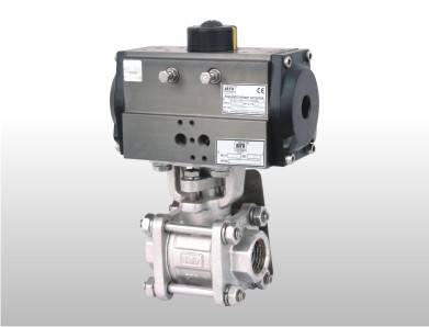
Three Piece Ball Valve
The three piece Ball Valve is the most adaptive ball valve design. In this design, the valve body contains three parts. The first and third parts hold end connections while the middle part holds the hollow ball, seat, and stem. All these parts are joined with bolts and screwed. Three Piece Ball Valve design allows maintenance activities without detaching the whole valve from the pipeline. Hence the three piece ball valves are the first choice of industrialists.
Floating Ball Valve
The Floating Ball Valve is the most common ball valve design in industrial piping systems. This type of ball valve is designed so that as the seat starts to wear the pressure from the media flowing through the valve will force the ball against the downstream seat to maintain a tight seal.
Trunnion Ball Valve
In trunnion mounted ball valves, the ball is set in place by bearings that prevent it from floating downstream. A spring-loaded seat mechanism ensures that the valve remains leak-tight as the seat necessarily begins to wear down.
V Shaped Ball Valve
The V-shaped Ball valve is also known as V port Ball Valve and V Notch Ball Valve. At the time of opening the v port ball valve, the small end of ‘v’ opens first. This allows accurate flow control and prevents water hammering. This design is generally used for robust construction because the high velocity of fluid can damage standard valves.
Full Bore & Reduced Bore Ball Valve
Full Bore Ball Valves contain the same diameter of a hollow Ball as the internal pipeline. It can be an inlet or outlet. While reduced bore ball valves mean the bore is smaller than the internal diameter of the pipe. The reduced bore ball valves are smaller in comparison to other ball valves, hence they are easy to install. A reduced bore ball valve is 30% lighter than a full bore ball valve so these are available at a low cost in the market. On the other side, the Full Bore Ball valves can control highly viscous media. Conversely, the reduced bore ball valves are only able to control normal media like water.
Multi Port Ball Valve
The Multi Port Ball Valves are generally 3-way or 4-way ball valves. These valves are usually employed for mixing and diverting purposes. The 3-way ball valve’s body has 3 ports and the ball is hollowed in an “L” shape. In these three ports, there is one for the inlet and the other one for the outlet, and the third one remains closed. This “L” shaped ball is used for diverting applications. There is also a “T” shaped ball available on the market. Both shaped balls work for the same purposes.
The four way ball valves are used for both mixing and diverting applications. This ball valve’s body contains four ports and the ball holes may vary. The hollowed ball is available in various shapes, “L” shape, “T” Shape, and “X” shape. As you can easily determine, the “L” & “X” shaped balls are used for diverting while the “T” shaped ball is used for mixing purposes. There is a 5 way ball valve also available to fulfill all your requirements.
Advantages of Ball Valve
Ball valves are adopted by broad industries. As ball valves are available in various types to match industrial valve requirements.
Here are some benefits of these valves:-
- Ball valves are best for quick action.
- Allows leakproof service
- Very small dimensions in comparison to other valves
- Lightweight, easy to carry
- Multi-designed flexibility to serve you
- Available in various sizes that allow flexibility in the selection of the appropriate valve.
- Able to perform under High Pressure & High Temperature with high-quality body materials
- Need minimum torque to operate
Disadvantages of Ball Valve
Where it is good in something the bad things are always there. It’s like two sides of a coin. With the advantages of ball valves, there are also some limitations to this valve.
- Not suitable for slurry media, because of cavities inside the valve body. It may jam the valve.
- Not suitable for throttling for a long time.
- Difficult to clean the main parts.
Industries using Ball Valves
Ball valves can perform in any industry where on/off application is required. They can control neutral and Corrosive liquids as well as gases. Few Industries below which are widely using ball valves:
Oil Refineries, Paint Industries, Petrochemicals, FMCG, Water Treatment Plants, Chemical Industries, etc.
Butterfly Valve
Like ball valves, butterfly valves are also quarter turn valves that require just a 90° rotation to come into action. In this valve, there is a flapping disc fit in the center of the valve. While operating the valve, this disc plays a barrier role in the flow. The central disc is similar to the wings of a butterfly, hence this valve is known as the butterfly valve.
Mechanism of Butterfly Valve
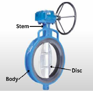
The butterfly valve is based on a simple mechanism. There are three main parts: valve body, central disc, and stem. The valve body contains all other parts like the valve seat and end connection. The central disc is set in the valve body with the central stem. This stem is connected to the outer hand lever that helps the disc rotation. When the disc is parallel to the flow, the valve opens and permits it to flow. When the disc is rotated 90° by the hand lever, it changes the position to perpendicular to the flow and closes the valve.
Butterfly Valve Types
There are two major types of butterfly valves: centric and eccentric. The centric butterfly valve is also known as the concentric and zero offset butterfly valve. The eccentric butterfly valve has three subtypes called single offset, double offset, and triple offset. Let’s explore all these three types of butterfly valves.
Concentric or Zero Offset Butterfly Valve
The concentric or zero offset butterfly valve is the basic or a general use butterfly valve. In this valve, the shaft is located in the center of the disc and bore. Because of this, the rotational disc is always in contact with or rubbing the seat during the opening and closing of the valve. This alignment causes friction at some points and wears out the seat with every movement of the disc.
Double Offset Butterfly Valve
Double offset Butterfly Valves are also called High-Performance Butterfly Valves. As the name suggests, the double offset butterfly valve has two offsets in comparison to a concentric butterfly valve. In this butterfly valve, the offset is achieved by the location of the central shaft. The central shaft is located slightly behind the disc. This arrangement ensures the continuous sealing surface on the disc.
The second offset is also achieved by the shaft position. In this arrangement, the shaft is located behind the disc as well as slightly on the right side of the pipe center. This offset provides contactless movement to the disc. When the valve is fully open, the central disc does not come in contact with the seat. Unlike the zero offsets, the double offset butterfly valve seat experiences less friction and the valve performs best with a long life cycle.
Triple Offset Butterfly Valve
Like a name, the triple offset butterfly valve has three offsets. The two offsets will remain the same as the double offset butterfly valve and the third offset will be achieved by the seat design. There is a conical seat fabricated to match the disc. This fabricated seat provides bubble tight sealing in high-pressure applications. With the other two offsets, the disc performs a frictionless operation for long durability.
Advantages of Butterfly Valve
Butterfly valves are acquired by many industries because of their simple mechanism. Their other benefits are like:
- Providing quick action needs just a quarter turn
- The disc is lighter than a ball used in a ball valve
- Need minimum structural support than a ball valve
- Required very little maintenance
- Quite reliable and very precise
- Easy to install
- Easy to use
Drawbacks of Butterfly Valve
When Butterfly Valves have some benefits, drawbacks also come with them. There are major points below:
- Even when the valve is fully opened, some portion of the disc keeps present in the flow
- Choking flow and Cavitation are the concerns
- Disc movement guides and affects flow turbulence
- Not suitable for throttling service for high-pressure flow even throttling service is limited to low differential pressure
Where to use Butterfly Valves?
Butterfly valves are a wide range of applications. These valves play a vital role in controlling the large volume of water applications and slurry applications. The following are some regular applications of Butterfly Valves:
- Cooling water, Air, Gases, Fire-protection, etc.
- Slurry and similar services
- Vacuum service
- High-pressure and high-temperature water and steam services
- Compressed air or gas applications
Plug Valve
The Plug Valve is the third and last member of the quarter turn valves. In this valve, there is a cylindrical or tapered plug inside the valve body. This plug controls fluid flow through the valve body. Plug Valves can be used for on-off applications, basic soft throttling, and diverting services.
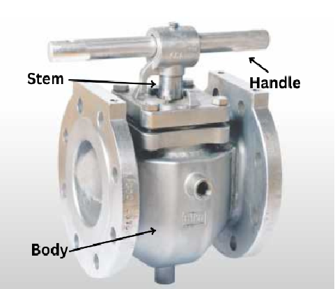
How does a Plug Valve Work?
In the valve body, there is a cylindrical hollow plug set that is connected to the stem or a hand lever. Like a ball valve, when the hollow plug’s hole is aligned to the flow direction it allows the fluid to pass away. When the plug rotates 90° the hole is set to perpendicular and the flow stops flowing. The plug in the plug valve plays a barrier role.
Types of Plug Valve
Plug Valves are sorted into two major types: Lubricated Plug valves and Non-Lubricated Plug Valves. The other types are based on the shape of the plug’s port: Rectangular Port, Round Port, and Diamond Port. Like a ball valve, plug valves are also available in multiway for mixing and diverting applications. Let’s explore each type of plug valve.
Lubricated Plug Valve
The Lubricated plug valve’s plug has a cavity in the middle along its axis. There is a lubricant chamber at the bottom of the valve and a sealant injection fitting on top of the valve, these two confirm the supply of lubricant. There is a small check valve under the injection fitting that prevents the sealant from escaping in the reverse when the sealant is injected into the cavity of the plug.
The plug surface gets constant lubrication by the sealant that moves from the center cavity via radial holes into lubricant grooves on the plug surface. We need this arrangement because many plug valves are made from all-metal construction. The gap around the plug may cause leakage, and if you decrease the gap further, that increases the friction, and the plug may get jammed inside the valve body.
The lubricant allows less force consumption to open or close the valve and provides smooth movement. It also helps the corrosion prevention of the plug. The lubricant for the plug valve must be compatible with the fluid of the pipeline. If the flow medium washes away the lubricant, it may damage the seal between the plug and the body and leads to leakage. Also, use a sealant that can withstand the temperature of the fluid flow. The lubricated plug valves come in a huge size range and are fit to work in high-pressure temperature applications. In some environments, these valves provide better corrosion resistance and are less prone to wear.
Non-Lubricated Plug Valve
As the name implies, the non-lubricated plug valves do not require lubrication or sealant. A non-metallics elastomeric sleeve or liner is employed in this type of valve. This sleeve is set in the body cavity of the valve. The polished cylindrical plug plays a wedge role and pushes the sleeve against the body.
The friction between the plug and the body is reduced because of the non-metallic sleeve. These valves are not suitable for high-temperature applications because of the non-metallic sleeve. Non-lubricated plug valves require less maintenance in comparison to lubricated plug valves.
Multi way or Multi port Plug Valve
Multi-port or Multi-way plug valves are designed for mixing and diverting applications. This valve is available in 2-way and 3-way types. The 3 way plug valves are commonly used for diverting purposes. The three-way plug valve used in diverting applications has one inlet source and two outlet sources. The operator will decide from which port the fluid will come out. The third port will remain idle till the operator diverts the flow toward this port.
Jacketed Plug Valves
There are also jacketed plug valves present in the market. That additional jacket system allows the media to remain in a molten state. This is an essential valve to control the fluid types that can be hard or solid in a short time.
Advantages of Plug Valves
- Plug Valves come in a simple design with very few parts
- Easy to open and close
- Allows repair and maintenance at the workplace
- It has the lowest flow resistance
- The plug Valve is reliable and leakproof.
Disadvantages of Plug Valves
- The plug Valve has high friction, because of this it requires a high torque amount in beginning to open or close the valve
- DN100 or larger Plug Valves require an actuator or a gearbox to operate
- Due to the conic plug, the flow narrows
- Plug valves are more expensive than ball valves.
Applications
Plug Valves can be seen in various industries. These valves can handle different fluids. These valves also perform best in slurry applications. The following are typical applications of plug valves:
- Gas, air, and steam applications
- Slurries like coal slurries, mineral ores, mud, and sewage applications
- Oil piping system
- Applications ranging from vacuum to high-pressure
Control Valve
The control valve is an intelligent power-operated valve used to adjust or manipulate the fluid flow like gas, oil, water, and steam. It is an important element of a control system and this is an example of the last control element. The control valve is by far the very common last and final control valve used in industry today. A Control Valve is a combination of two components: the Valve and the Actuator.
Control Valve Operation
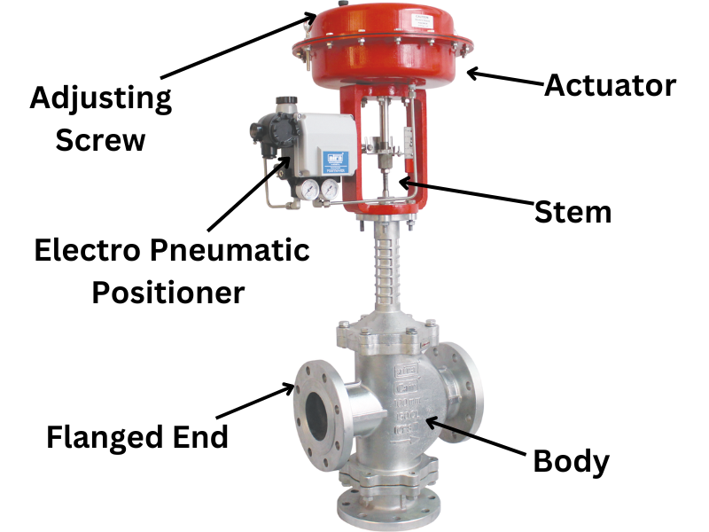
Control Valves can not be operated manually. For precise control over the fluid, these control valves are operated by either an electric actuator or a pneumatic actuator only.
When the valve operator enters the command in a controller like a PLC, the PLC sends a signal to the control valve. There is a converter which is also known as an I/P transducer, that reads the signals and converts the electric signal to pneumatic pressure. Because of this, the pneumatic diaphragm moves as per the operator’s inputs. Hence the control valves provide accurate control over the fluid.
Control Valve Types
Control Valves are available in various types. There is a diaphragm control valve, angle type, or Y-type control valve, Globe type on/off valve, High-pressure Control Valve, High-temperature control valve, and many more. There are also 2/2 and 3/2-way control valves available for mixing and diverting purposes.
Control Valve Using Industries
Control Valves are necessary for many industries. The oil and gas industry is one of the most well-known applications using control valves. Control Valves control operating conditions like liquid levels, pressure, flow, and temperature. Following are a few examples of control valves using industries:
- Textile Industry
- Pulp and Paper
- Chemical Plants
- Paint Industry
- Pharmaceuticals, etc.
Solenoid Valve
The Solenoid plays a key role in solenoid valves. A solenoid Valve can take place where the fluid flow has to be controlled automatically. There are numerous varieties of solenoid valves that offer a broad selection and choices. There is an advanced mechanism behind this valve that controls the fluid flow. These valves use electricity and coils that create a magnetic field. Solenoid Valves control the flow with the help of this electromagnetic field. Let’s take a look at the mechanism of solenoid valves and get an idea about how they work.
How does a Solenoid Valve Work?
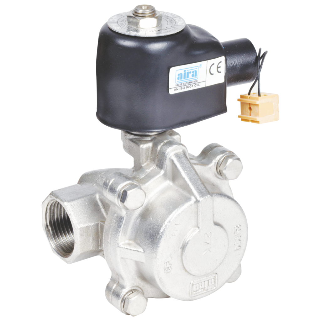
Solenoid valves are control valves that are electrically energized to come into action. There is an electromagnetic coil and a plunger or plug in the valve body. This plunger is used as a barrier. When the coil is energized, a magnetic field yields. This magnetic field pulls a plunger or plugs against the action of the spring. The spring pushes the plunger back to its original position when the coil is de-energized and the magnetic field ends. In this way, the solenoid valves control the fluid and allow or stop the flow as per requirement. There are several types of solenoid valves present in the valve market. A few of them will be mentioned below.
Types of Solenoid Valve
There are several types of solenoid valves. As per the plunger position, this valve is available as normally open and normally closed. As per the mechanism, this valve is available as direct-acting, pilot-operated, and semi pilot operated. Let’s explore all of this one by one.
Normally Open & Normally Closed Solenoid Valves
As the name indicates when the diaphragm solenoid valve stays open in idle conditions that are called the Normally open solenoid valve. When the solenoid valve is energized the plunger or plug goes forward toward the coils and stops the fluid flow. When the valve is de-energized, the spring pushes back the plunger to its original position and keeps allowing fluid to flow.
On the other hand, a normally closed solenoid valve stops the fluid from flowing in an idle state. When the solenoid valve is energized, the plug or plunger pulls up and allows fluid to pass through. This can be fit at the end of the pipeline and used as an outlet.
Direct Acting Solenoid Valve
Direct acting Solenoid Valve is also known as a zero-rated solenoid valve. Direct-acting solenoid valves use direct armature movement to open or close the solenoid valve. The plunger inside the valve body directly opens and closes the orifice. All operations are performed directly in this type of solenoid valve. This valve starts at its maximum rated pressure and is operated to close flow or zero psi.
Advantages of Direct-Acting Solenoid Valve
- Best fit for negative pressure circuits
- Designed to manage debris particles
- Compact in size and economy rates
- available in normally open and normally closed versions
- Miniature versions are present for high pressures
Pilot Operated Solenoid Valve
Pilot Operated Solenoid Valves utilize the dissimilar pressure of the media over the valve ports to open and close. These valves are also known as diaphragm solenoid valves. These valves offer high flow rates and can work at a higher pressure and temperature range, with low power consumption.
A diaphragm solenoid valve with pilot control manages the use of a small compartment just above the diaphragm to assist in the operation of the valve. In a normally closed valve, the fluid is allowed to enter that compartment through a small orifice in the inlet port. This action compresses the diaphragm and forces it against the seat to maintain the closing seal.
When the pilot solenoid is energized, the diaphragm is moved upwards against the spring pressure, and the pilot fluid in the compartment is forced back via the orifice in the inlet port where it re-joins the main flow through the valve body.
Advantages of Pilot Operated Solenoid Valves
- Best fit for a large flow
- Lower electrical power consumption
- Pressure assists in valve operation
- Minimum pressure differential requires
- Cost-effective for higher flow rates.
Semi Pilot Operated Solenoid Valve
Semi direct acting, Semi-diaphragm, or Semi-Pilot operated Solenoid Valves combine the properties of direct and indirect valves. This function allows it to work from zero bar and also can handle a high flow rate. These look similar to indirect valves and also have a moveable diaphragm with a small orifice and pressure chambers on both sides. The main difference is that the solenoid plunger is connected to the diaphragm.
When the solenoid energized and the plunger lifted, the diaphragm also pulled up and opened the valve. At the same time, the second orifice is also opened up by the plunger movement. This second orifice has a slightly larger diameter than the first one. Due to this, the pressure in the chamber above the diaphragm drops, and the diaphragm is pulled up not only by the plunger but also by the pressure differential.
This complex mechanism of the valve operates from zero bar and can control large flow rates. Generally, semi diaphragm solenoid valves have more powerful coils than diaphragm operated solenoid valves. This valve is also called assisted lift solenoid valve and semi direct solenoid valve.
Solenoid Valve Applications
Solenoid Valves are utilized in various industries. These valves are used in machinery, devices, and equipment such as refrigerators and valve automation. Solenoid Valves are widely used to control High pressure media like Air, Water, Hot water, Steam, Chemicals, Oil, Gas, Vacuum, and other high temperature fluids. These valves are also useful in hazardous environments.
Safety Valve
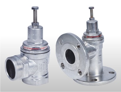
Unlike regular valves, the safety valves are designed with an intelligent mechanism that ensures the safety of other workers by preventing accidents. This valve is ideal for boilers, Steam, and other high-pressure media. The main purpose of this valve is to release extra unnecessary pressure from the vessel and reclose it to keep the desired pressure as per the process needs. This valve is also called the Pressure Relief Valve and Pressure Safety Valve. There are two types of safety Valves available in the market: Angle type Silent Safety Valve and POP type Safety Valve. This valve is for safety purposes, so the government has set the national standard for Pressure Relief Valves. These valves are designed as per the Indian Boiler Regulation. In short, this type of valve is called an IBR approved Safety Valve.
Advantages of Pressure Relief Valve
This valve declines worries about causes of overpressure of Thermal Expansion, Chemical Reactions, Heat Exchanger Tube Rupture, and Cooling System Failure. Also, maintains required and adaptive pressure for system operation.
Pressure Reducing Valve
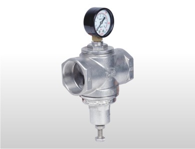
When the outlet flow pressure is very high, the pressure reducing valve decreases the flow to get precise control. A pressure reducing valve which is also called a pressure reducing regulator is a self operating valve. This valve is necessary to reduce the high pressure from the outlet pipe. Mostly this valve is installed in high-rise buildings to reduce the water flow. This valve is also used for steam applications.
A pressure reducing valve does not require any force or energy to come into action. It senses the high pressure and reduces it to the set point.
Here are some main functions of a Pressure Reducing Valve:
- In a steam system:- pressure reducing valves are utilized to get specific downstream pressure. These valves automatically balance the output pressure during inlet pressure fluctuation.
- In high rise buildings:- correct Pressure Reducing Valves can prevent water hammering effects.
- The Pressure Reducing Valves are able to take rapid action by sensing and adjusting based on the downstream pressure.
Advantages of Pressure Reducing Valve
There are many advantages of pressure reducing valves, the main benefits are noted below:
- Self operated, does not require any power source
- No bunch of mechanisms, Simple design
- Reliable with minimum maintenance
- Quick Response
High Pressure Valve
Despite many industrial valves, there are some high pressure valves serving the industry. These valves are specially designed to control vast stored fluids like water, air, oil, gas, etc. Which will flow with extremely high pressure. Gate Valve, Knife-Edge Gate Valve, Needle Valve, Piston Valve, Disc Check Valve, Non-Return Valve, and Globe Valve, are on the list. Let’s explore each of them.
Gate Valve
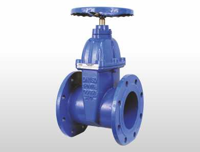
Gate Valves are used for on-off applications. It is typically utilized in water supply systems. The gate valves are linear motion isolation valves. This valve got its name from its closure element. This element slides into the fluid flow to shut off, and because of this act like a gate, so called ‘gate valve’. Gate valves are mainly utilized in water supply networks. It is used for water supply maintenance, repair works, and new installations, as well as to re-route the water flow through the pipeline.
Gate Valve Mechanism
There is a threaded stem that connects to the inside gate or wedge. By rotating the threaded stem, the connected wedge moves up-down. To stop the flow, this gate will be entered in the middle of the flow and vice versa.
Knife Edge Gate Valve
As the name suggests, there is a knife edge shaped gate valve. Similar to an ordinary gate valve, this is also a linear movement valve. There is a sharp disc used as a barrier in this knife edge gate valve. This sharp disc is connected to either a threaded or non-threaded stem. The threaded stem connected to the gear and the non-threaded stem connected to the pneumatic cylinder. With the help of this stem, the knife edge gate slides.
The wastewater treatment plants, chemical plants, mining, and cement plants mostly use knife edge gate valves. Apart from this many industrial plants which consume slurry materials and Un-flammable viscous fluids like FMCG factories also use Knife Edge Gate Valves.
Needle Valve
The needle valve is also known as a Plunger Valve. The needle valve gets its name from its narrow needle like plug. This valve is small in size and gives precise control over the flow. In this valve, there is a threaded stem connected to a sharp needle and the handle on the other end. During rotation of the handle, the needle lifts up and allows the fluid to flow and vice versa. Needle valves can control high-pressure media. It can be utilized for Air, Water, Oil, and Gas applications.
Piston Valve
Piston Valves are placed for fully open or fully closed on/off regulations. These valves are mainly used on fluids that lead to excessive seat wear. Piston valves are generally actuated manually. These valves have a long life cycle and require less maintenance. Piston valves are not designed for throttling applications.
There is a piston used as a barrier in this valve. The valve body is designed in a specific “s” shape. Where the inlet port is below the outlet port. The sliding piston separates them up and down. When the valve is fully opened, only the lower surface of the piston gets in contact with the fluid. The rest of the valve body is protected by the upper sealing rings. That’s why the sealing surfaces are safe from erosion by fluid flow.
Benefits of Piston Valve
- Zero leakage
- Long Life Cycle
- Maintenance not required
- Easy to Install
- Free from asbestos
- Replaceable inline valve rings
- Excellent control over the flow
Disc Check Valve (Non Return Valve)
Disc Check Valves are Non Return Valves made from steel. Its name comes from its working capability. This valve prevents reverse flow. That’s why it’s called a Non-return Valve. It is also known as NRV. These valves are at cheap rates rather than other valves as they are small and lightweight. There is a spring loaded disc that allows the fluid to flow in only one direction. The spring is set towards the outlet port and the disc is set at the inlet port. By the pressure of the fluid flow, the spring squeezes, and the disc permits it to flow. When the pressure drops, the spring pushes the disc toward the inlet port and prevents the fluid from returning from the outlet port. The disc check valve can be set in any position.
Globe Valve
A Globe Valve is a linear motion control valve. It is basically designed to start, stop and regulate the fluid flow. There is a disc connected to a threaded stem. With the help of this stem, the disc dive into the flow path to completely block the passageway and close the valve. By rotating the stem, the disc slides up gradually and allows the fluid to pass through. Because of its design, gate valves exhibit higher flow pressure drop than other straight through valves. The globe valve is acquired where the pressure drop is not a concern.